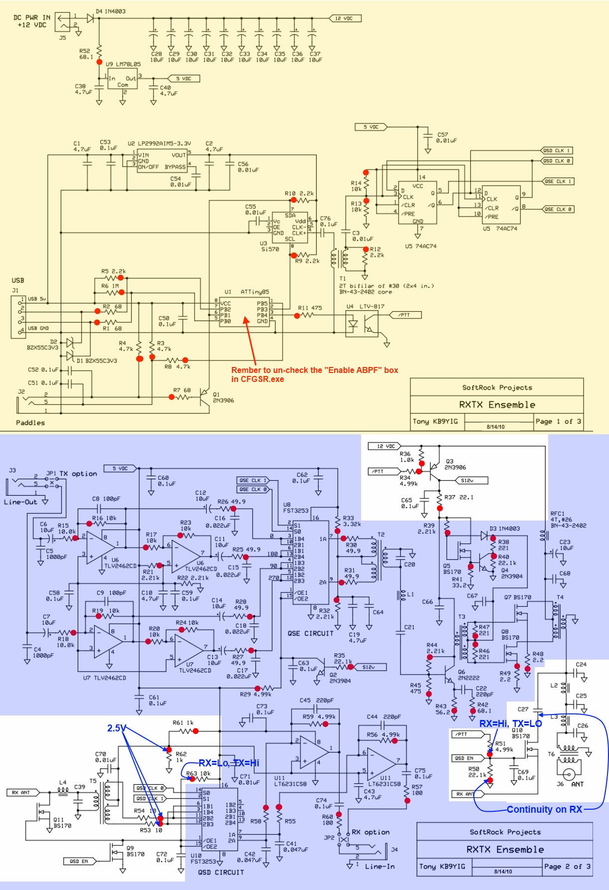
Ensemble RXTX - RF I/O and Switching
Band: 30, 20, 17m
Introduction
Band Specific Components
This stage involves band-specific components and is currently configured for the 30, 20, 17m band. If you need to configure this page for a different band, click on the "Band" tab in the menu above. This would take you to the home page, where you can select the new band and then return to this page.
General Info About the Stage
Here is a sketch provided courtesy of Bob, G8VOI. On 20 March 2011, supporting the following description:

HamNation Video of this Stage's Build
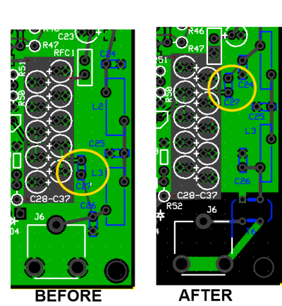
The RXTX Ensemble board with a date of 4/4/10 had a wiring error concerning the point in the circuit where the RX BPF antenna connection is made.
The author got caught by this and reinstalled C27 to the underside of the board (shown in the bottom view of the completd board . Production boards will not have this problem. The "Before" board had C27 located differently and was missing the antenna isolation transformer (thus, you won't see that transformer in the completed photos near the bottom of this page.
Additionally, a recent change to the layout of T6 causes the positions of the ground and "hot" leads of the T6 secondary to switch:
This stage handles the RF input and Output paths, along with the switching from Receive to Transmit. The radio defaults to the RX mode. When a PTT signal is sent down the USB line to the ATTiny 85 in the Local Oscillator stage, that signal is passed through to the radio across the galvanically isolated boundary beteen the digital and analog side of the rig via the optoisolator, U4.
In RX the /PTT line is pulled toward 12 volts which results in Q10 conducting RX signal and Q9 pulling the /OE pins of U10 low to enable the QSD operation.
In TX the /PTT line is pulled low by optoisolator U4 and Q9 and Q10 are not conducting. This results in Q11 conducting and shorting the RX input to ground. It also results in pulling the base of Q3 down, turning it on and generating the S12V supply to the PA on transmit.
This allows the rig to use the path to the antenna jack by RX and TX. As a matter of convenience, we install all of that path in this stage.
This stage includes winding a toroidal transformer and three toroidal coils. The builder needs to be very careful to note the toroid requirements, which are band-specific. Be sure to use the right toroid, as indicated in the Bill of Materials. Check:
- The color: "Tnn-2" is red; "Tnn-6" is yellow)
- The size: "T25-n" is a 0.25" OD toroid; T30-n" is a 0.30" OD toroid; and "T37-n" is 0.37"
If you have no experience with winding and installing toroidal inductors, you are strongly encouraged to review the WB5RVZ Instructions for Winding and Installing such inductors.
Theory of Operation
Summary Build Notes
Stage Schematic
Go to Top of Page
Click here for full schematic
(Red dots represent the "hairpin" (or left-hand or topmost) lead of the component)
Board Layouts
Board Top
Go to Top of Page
Board Bottom
Go to Top of Page
RF I/O and Switching Bill of Materials
(30, 20, 17m band option)
(details for installation of each component are provided in the step instructions, further down the page)
Be sure to use the correct wire gauge when winding inductor(s)
Note: R53 and R53 were inadvertently left out of the photos of the completed board topside (they appear in the following stage, RF Mixer)
| Check | Type | Category | Component | Count | Marking | Image |
|---|---|---|---|---|---|---|
| ☐ | Capacitor | Ceramic | 150 pF 5% | 2 | 151 (may be blue or tan) |
|
| ☐ | Capacitor | Ceramic | 180 pF 5% | 1 | 181 |
|
| ☐ | Capacitor | Ceramic | 220 pF 5% | 1 | 221 |
|
| ☐ | Capacitor | Ceramic | 330 pF 5% | 1 | 331 |
|
| ☐ | Capacitor | SMT 1206 | 0.01 uF | 1 | (smt) no stripe |

|
| ☐ | Capacitor | SMT 1206 | 0.1 uF | 3 | (smt) black stripe |

|
| ☐ | Connector | BNC-RA | bnc connector pcb (rt-angle) | 1 |

|
|
| ☐ | inductor | Toroid | T25-6 toroid core | 2 | yellow |

|
| ☐ | inductor | Toroid | T37-6 toroid core | 2 | yellow |
|
| ☐ | inductor | Binocular core | BN-61-2402 (no Markings!) | 1 | none |
|
| ☐ | inductor | Xfrmr | 0.6uH: 14T/2x7T bifilar #30 on T25-6 (yellow) 8" | 1 | yellow | (magnetic wire) |
| ☐ | Inductor | Coil | 0.6uH: 14T #26 on T37-6 (yellow) | 2 | yellow | (magnetic wire) |
| ☐ | Inductor | Coil | 0.78uH 17T #30 on T25-6 (yellow) | 1 | yellow | (magnetic wire) |
| ☐ | Inductor | xfrmr | 4T bifilar #30 on BN-61-2402 | 1 | (magnetic wire) | |
| ☐ | Resistor | 1/4W | 10 ohm 1/4W 1% | 2 | br-blk-blk-gld-br |

|
| ☐ | Resistor | 1/4W | 22.1 ohm 1% | 1 | red-red-brn-gld-brn |

|
| ☐ | Resistor | 1/4W | 1 k 1/4W 1% | 3 | br-blk-blk-br-br |

|
| ☐ | Resistor | 1/4W | 4.99 k 1/4W 1% | 2 | y-w-w-br-br |

|
| ☐ | Resistor | 1/4W | 10 k 1/4W 1% | 1 | br-blk-blk-r-br |

|
| ☐ | Transistor | TO-92 | 2N3906 PNP transistor | 1 | 2N3906 |
|
| ☐ | Transistor | TO-92 | BS170 N-Channel Enhancement Mode FET | 3 | BS170 ESD!!! |
|
Go to Top of Page
Detailed Build Steps
Step_Install SMT Capacitors
| Check | Designation | Component (top/bottom) | Orientation | Marking | Image | Band | Notes |
|---|---|---|---|---|---|---|---|
| ☐ | C65 | 0.1 uF ((bottom)) | (smt) black stripe |
|
any | ||
| ☐ | C69 | 0.1 uF ((bottom)) | (smt) black stripe |
|
any | ||
| ☐ | C70 | 0.01 uF ((bottom)) | (smt) no stripe |
|
any | ||
| ☐ | C72 | 0.1 uF ((bottom)) | (smt) black stripe |
|
any |
Go to Top of Page
Step_Wind and Install Coils
Inductor Information
Common Techniques:
- Wire Gauge: remember the higher the number, the thinner the wire. E.g., #30 wire is thinner than #26 wire.
-
One turn:
- For toroids, one turn is a single pass through the center hole.
- For binocular cores, one turn is a pass in which the wire goes in the bottom, comes out the top, goes back in the other hole at the top, and comes out the other hole at the bottom.
- Bi (tri) filar means 2(3) equal lengths of wire. You get the bi(tri)filar strand by taking the length of wire specified for the primary winding, folding it into half(thirds), twisting it to 3~ twists per inch, and winding it over the primary winding. One end of such a strand will have two(three) leads; the other end will have a "hairpin" bend (and a single lead in the case of tri-filar).
- Multi-filar windings are usually done AFTER the uni-filar winding is done.
- Windings shoud be evenly spaced and ideally made such that the winding covers ~345 degrees of the toroid
- Inductance values given are for the single (uni-filar) winding. They are provided to help verify turn counts and core material selected. It's often reported inductances are higher using the theoretical number of turns as calculated by the manufacturer's windings calculator tool, e.g. http://toroids.info/. Normally though these are not too critical, especially with the LF bands antenna noise will still be seen.
-
Toroid nomenclature provides the outside diameter of the toroid (in hundredths
of an inch - the "30" in "T30-2"), and material code (the "2" in "T30-2").
Color codes used in these kits are:
- 2=Red
- 3=Gray
- 6=Yellow
- 7=White
- 10=Black
- 12=Green (with White on opposite side)
Inductors In This Step
L2COIL: 0.6uH: 14T #26 on T37-6 (yellow)
Using approximately 10 inches of #26 wire, wind 14 turns on a 0.37 inch od T37-6 (yellow) ferrite. Inductance = 0.60 uH.
COIL: 0.6uH: 14T #26 on T37-6 (yellow)
Using approximately 10 inches of #26 wire, wind 14 turns on a 0.37 inch od T37-6 (yellow) ferrite. Inductance = 0.60 uH.
COIL: 0.78uH 17T #30 on T25-6 (yellow)
Using approximately 9 inches of #30 wire, wind 17 turns on a 0.25 inch od T25-6 (yellow) ferrite. Inductance = 0.78 uH.
Wind and install each of the three coils. Recall that any pass of the wire through the toroid's core counts as ONE turn. Refer to the WB5RVZ coil winding instructions for details on how to wind and prepare/install single-winding coils.
Once you have installed the the coils (L2 and L3 and L4), you can test your soldering by checking the continuity of the winding for each coil as follows (using points on traces connecting the coils to other components - these tests are most easily done PRIOR to installing the remaining components in this stage):
| Coil | First Point | Second Point |
|---|---|---|
| L2 | C27(top) | C25 (right) |
| L3 | C25 (right) | C26 (bottom) |
| L4 | C27 Bottom | C39 (top) (note Power must be on and transistors installed.) |
Note: L4 is switched on. You will need to power the board and let the switching transistors provide continuity on the path to/through L4.
| Check | Designation | Component (top/bottom) | Orientation | Marking | Image | Band | Notes |
|---|---|---|---|---|---|---|---|
| ☐ | L2 | 0.6uH: 14T #26 on T37-6 (yellow) (top) | yellow |
 |
30, 20, 17m | ||
| ☐ | L2core | T37-6 toroid core (top) | yellow |
|
30, 20, 17m | ||
| ☐ | L3 | 0.6uH: 14T #26 on T37-6 (yellow) (top) | yellow |
|
30, 20, 17m | ||
| ☐ | L3core | T37-6 toroid core (top) | yellow |
|
30, 20, 17m | ||
| ☐ | L4 | 0.78uH 17T #30 on T25-6 (yellow) (top) | yellow |
|
30, 20, 17m | ||
| ☐ | L4core | T25-6 toroid core (top) | yellow |
|
30, 20, 17m |
Go to Top of Page
Step_Wind and Install Transformers
Inductor Information
Common Techniques:
- Wire Gauge: remember the higher the number, the thinner the wire. E.g., #30 wire is thinner than #26 wire.
-
One turn:
- For toroids, one turn is a single pass through the center hole.
- For binocular cores, one turn is a pass in which the wire goes in the bottom, comes out the top, goes back in the other hole at the top, and comes out the other hole at the bottom.
- Bi (tri) filar means 2(3) equal lengths of wire. You get the bi(tri)filar strand by taking the length of wire specified for the primary winding, folding it into half(thirds), twisting it to 3~ twists per inch, and winding it over the primary winding. One end of such a strand will have two(three) leads; the other end will have a "hairpin" bend (and a single lead in the case of tri-filar).
- Multi-filar windings are usually done AFTER the uni-filar winding is done.
- Windings shoud be evenly spaced and ideally made such that the winding covers ~345 degrees of the toroid
- Inductance values given are for the single (uni-filar) winding. They are provided to help verify turn counts and core material selected. It's often reported inductances are higher using the theoretical number of turns as calculated by the manufacturer's windings calculator tool, e.g. http://toroids.info/. Normally though these are not too critical, especially with the LF bands antenna noise will still be seen.
-
Toroid nomenclature provides the outside diameter of the toroid (in hundredths
of an inch - the "30" in "T30-2"), and material code (the "2" in "T30-2").
Color codes used in these kits are:
- 2=Red
- 3=Gray
- 6=Yellow
- 7=White
- 10=Black
- 12=Green (with White on opposite side)
Inductors In This Step
T5XFRMR: 0.6uH: 14T/2x7T bifilar #30 on T25-6 (yellow) 8"
Primary: Using approximately 8 inches of #30 wire, wind 14 turns on a 0.25 inch od T25-6 (yellow) ferrite.
Secondary: Using a total of 8 inches of #30 wire, wind 7 turns , bifilar, on the ferrite in the same direction as the primary winding. Inductance of the single winding (usually the primary) is 0.60 uH.
XFRMR: 4T bifilar #30 on BN-61-2402
Primary/Secondary using a total of approximately 7 inches of #30 wire, wind 4 turns , bifilar, on a BN-61-2402 ferrite.Inductance of the single winding (usually the primary) is 4.00 uH.
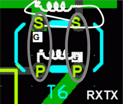
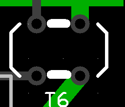
ALERT! Original Ensemble RXTX pcb layouts have an error in the placement of the leads for T6, the Antenna isolation transformer. If the antenna isolation transformer is not connected properly then the outer of the antenna coax will be prone to common mode currents causing noise pickup on receive and local emissions on transmit. The principle is that the grounded side of the isolation transformers should go to the same end of the primary and secondary: The two wires that come from the same hole in the binocular core represent one end of the primary and of the secondary. One of those two ends must be switched (for one of the windings, primary orsecondary - your choice). The graphic to the right shows the binocular core and its two holes; the winding that was switched was the secondary. See the article by Alan G4ZFQ for IMPORTANT details.
Wind and install toroidal transformers T5 and T6. See the WB5RVZ Instructions for Toroidal Transformers for important, detailed instructions on how to wind and install toroidal transformers..
NB: later boards have the position of the hot and common secondary leads of T6 reversed, See caveat at the top of the page.
"Correct" installation: both wires exiting the same binocular core hole must go to the same kind of connection - 'hot' (signal) or 'cold' (ground). with the core oriented as shown by the stencilling, both wires exiting the left-hand hole of the core need to go to 'hot' points (signal path and center pin of BNC), and both wires exiting the right-hand hole of the core need to go to 'cold' points (ground plane and outer shell of BNC).
After installing the transformers, you should check the primary and secondary windings for continuity with your ohmmeter, using the following testpoints connected via traces to the windings (these tests are easier done prior to installing the remaining components in this stage):
| Coil | First Point | Second Point |
|---|---|---|
| T5 Primary | C39 (left) | C39 (right) |
| T5 Secondaries | R53 (right) | R54 (bottom) |
| T6 Secondary | C26 (bottom) | C26 (top) |
| T6 Primary | Center conductor of J6 | Shield side of J6 |
| Check | Designation | Component (top/bottom) | Orientation | Marking | Image | Band | Notes |
|---|---|---|---|---|---|---|---|
| ☐ | T5 | 0.6uH: 14T/2x7T bifilar #30 on T25-6 (yellow) 8" (top) | yellow |
|
30, 20, 17m | ||
| ☐ | T5core | T25-6 toroid core (top) | yellow |
|
30, 20, 17m | ||
| ☐ | T6 | 4T bifilar #30 on BN-61-2402 (top) |
|
30, 20, 17m | |||
| ☐ | T6core | BN-61-2402 (no Markings!) (top) | none |
|
30, 20, 17m |
Go to Top of Page
Step_Install Topside Transistors
| Check | Designation | Component (top/bottom) | Orientation | Marking | Image | Band | Notes |
|---|---|---|---|---|---|---|---|
| ☐ | Q03 | 2N3906 PNP transistor (top) | 2N3906 |
|
any | ||
| ☐ | Q09 | BS170 N-Channel Enhancement Mode FET (top) | BS170 ESD!!! |
|
any | ||
| ☐ | Q10 | BS170 N-Channel Enhancement Mode FET (top) | BS170 ESD!!! |
|
any | ||
| ☐ | Q11 | BS170 N-Channel Enhancement Mode FET (top) | BS170 ESD!!! |
|
any |
Go to Top of Page
Step_Install Band-Specific Capacitors
| Check | Designation | Component (top/bottom) | Orientation | Marking | Image | Band | Notes |
|---|---|---|---|---|---|---|---|
| ☐ | C24 | 150 pF 5% (top) | 151 (may be blue or tan) |
|
30, 20, 17m | ||
| ☐ | C25 | 330 pF 5% (top) | 331 |
|
30, 20, 17m | ||
| ☐ | C26 | 150 pF 5% (top) | 151 (may be blue or tan) |
|
30, 20, 17m | ||
| ☐ | C27 | 180 pF 5% (top) | 181 |
|
30, 20, 17m | ||
| ☐ | C39 | 220 pF 5% (top) | 221 |
|
30, 20, 17m |
Go to Top of Page
Step_Install Topside Resistors
| Check | Designation | Component (top/bottom) | Orientation | Marking | Image | Band | Notes |
|---|---|---|---|---|---|---|---|
| ☐ | R34 | 4.99 k 1/4W 1% (top) | W-E | y-w-w-br-br |
|
any | |
| ☐ | R36 | 1 k 1/4W 1% (top) | W-E | br-blk-blk-br-br |
|
any | |
| ☐ | R37 | 22.1 ohm 1% (top) | W-E | red-red-brn-gld-brn |
|
any | |
| ☐ | R51 | 4.99 k 1/4W 1% (top) | N-S | y-w-w-br-br |
|
any | |
| ☐ | R53 | 10 ohm 1/4W 1% (top) | flat-horiz | br-blk-blk-gld-br |
|
any | |
| ☐ | R54 | 10 ohm 1/4W 1% (top) | S-N | br-blk-blk-gld-br |
|
any | |
| ☐ | R61 | 1 k 1/4W 1% (top) | W-E | br-blk-blk-br-br |
|
any | |
| ☐ | R62 | 1 k 1/4W 1% (top) | W-E | br-blk-blk-br-br |
|
any | |
| ☐ | R63 | 10 k 1/4W 1% (top) | W-E | br-blk-blk-r-br |
|
any |
Go to Top of Page
Step_Install BNC Connector
| Check | Designation | Component (top/bottom) | Orientation | Marking | Image | Band | Notes |
|---|---|---|---|---|---|---|---|
| ☐ | J6 | bnc connector pcb (rt-angle) (top) |
|
any |
Go to Top of Page
Completed Photos
View of Completed Topside
View of Completed Underside
Go to Top of Page
There is a "patch" shown on the bottom view necessitated by the fact that the author's board was a prototype and had incorrect mounting for C27. This should not bother builders using the production boards.
Author inadvertently left R53 and R54 out of the completed board in this phase. Those components should actually be installed in this phase.
Progressive Schematic
Where are we in our progress towards the finish line? Click here to view the entire schematic with the completed stages shaded in a yellowish tinge and the remaining stages tinted in blue (the current stage is untinted).
Test the RF I/O and Switching Stage
RF I/O and Switching - Current Draw
Power up the board and check the current draw
Go to Top of Page
Test Steps (if any)
| Step | Test Point | UOM | Nominal | Author's | Builder's |
|---|---|---|---|---|---|
| 0 | Current draw | mA | <20 | 16.1 |
Go to Top of Page
RF I/O and Switching - Voltage Divider Test
R61 and R62 form a voltage divider off of the 5 volt rail.
The output of that voltage divider go to the secondary windings of T5 to Resistors R53 and R54
Apply 12V power to the board and measure the voltage at the hairpin lead of R62.
Troubleshooting the Voltage Divider
Note: if you installed ALL SMT components prior to beginning the stage-by-stage build, you will likely find your voltage at R62 hairpin a bit lower than the nominally expected value. See the thread on the Yahoo Softrock-40 reflector about this test.
Go to Top of Page
Test Steps (if any)
| Step | Test Point | UOM | Nominal | Author's | Builder's |
|---|---|---|---|---|---|
| 1 | R62 hairpin lead (wrt regular ground) (with V+ = 12.7V) | Vdc | 2.5 | 2.48 | |
| 2 | R53 left lead (wrt regular ground) | Vdc | 2.5 | tbd | |
| 3 | R54 hairpin lead (wrt regular ground) | Vdc | 2.5 | tbd |
Go to Top of Page
RF I/O and Switching - RF Switching Testing
Voltages are measured WRT (regular) ground (R50 hairpin)
Test the PTT switching from the default RX/QSD enabled to the switched TX/QSE enabled.
Requires USB connected and 13V power applied to the board.
Test for default (RX) and then use SDR Software to activate PTT and test for QSD disabled OFF.
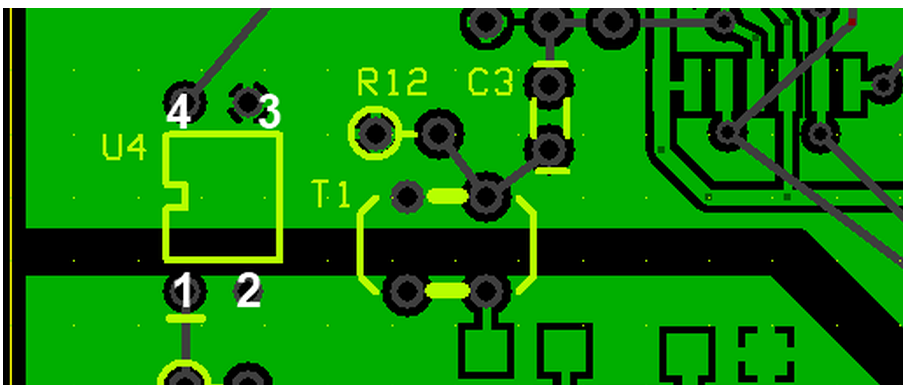 (As an alternative to using the SDR Software to activate PTT, you can use a cliplead to ground the top left-hand lead of U4, activating PTT.)
Enabling PTT also should pull the base of Q3 down, turning it on and generating the S12V supply to the PA on transmit.
Bob, G8VOI, has provided a nice little trouble-shooting schematic to aid for those who may experience problems with this stage.
Go to Top of Page
Test Steps (if any)
| Step | Test Point | UOM | Nominal | Author's | Builder's |
|---|---|---|---|---|---|
| 0 | Default (RX Activated): Point A | Vdc | High (9 - 12 Vdc) | 9.86 | |
| 1 | Default (RX Activated): Point B (R63 hairpin) | Vdc | Low (~ 0) | 0 | |
| 2 | PTT Activated: Point A | Vdc | Low (~ 0) | 0 | |
| 3 | PTT Activated: Point B | Vdc | High (~ 5) | 4.95 |
Go to Top of Page
RF I/O and Switching - RF Path Testing
There are two approaches to testing the RF Path. One involves testing for continuity through the switching transistors. This approach calls for testing continuity with the board powered up, something which some are understanably uncomfortable doing. As Bob, G8VOI puts it:
"Personally that is one particular test which I have severe reservations about, and think it might well contribute to a number of the failures of FETs that some people have experienced in that area.
I suspect it might depend on the terminal voltage of the meter being used, polarity, or simply slipping and shorting to something else.
I think it is sufficient just to measure the voltage on the junction of R51 / R50, i.e the gate of Q10 when the PTT is inactive, should be around 8V which will turn Q10 on.
Most people have successfully carried out that test as described in Robby's notes without any ill effects, but there have also been a number of unexplained failures of Q10 and Q9.
I could be totally wrong of course :)
The other approach is, as Bob suggests, simply testing that Q10 is getting the proper voltage to switch it ON.
Which approach is selected is up to the builder.
Continuity Test Under PowerApproach
Using your ohmmeter, test for continuity along the RF path for the RX. The path can be tested between C27 (bottom pin - point A) and regular ground (hiarpin lead of R50).
.
You must have the USB powered up and the board's 12V power applied to test the path from C27 (point A) through to the other (ground) end of T5 (ground, point B).
Note: the testpoint "A", shown on the graphic, MUST be POSITIVE with respect to test point "B" in order to correctly assess the continuity from A to B. Normally, the positive lead will be the red lead of your ohmmeter. If you get an OPEN reading, try reversing the leads of your ohmmeter..
Q10 Voltage Approach
With power applied (USB and regular 12V), measure the voltage at the junction of R51 and R50 (hairpin of R51). It should be approximately 8V
Additional Voltage Tests
For a more thorough test of the voltages for switching for RX and/or TX, refer to this page courtesy of Bob, G8VOI.
Go to Top of Page
Test Steps (if any)
| Step | Test Point | UOM | Nominal | Author's | Builder's |
|---|---|---|---|---|---|
| 0 | Continuity from Point A to Point B | ohm | 0 | 0 | |
| 1 | Hairpin of R51 (Q10 switching voltage - PTT is inactive) | Vdc | ~8 | 8.04 |
Go to Top of Page