Common Component Monting Tips
Introduction/Contents
This page provides guidance to the builder on common components encountered Introductionbuilding the Softrock series of SDR kits. Click on the links below for techniques/tips on:
- Preparing and Installing Resistors
- Identifying and installing Ceramic Capacitors
- Installing SMT Capacitor Chips
- Installing SMT IC Chips
- Inductors-General
Resistors
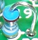
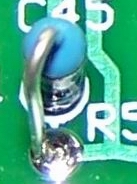
The resistors are mounted with one of five orientations. The first four are the "hairpin" style, where the body of the resistor is snugged up against the board at the location indicated by the silkscreened circle and the other lead is bent into a hairpin shape and inserted into the hole pointed to by the small line on the resistor's silkscreened circle.
You can put a neat hairpin on a resistor lead by holding the resistor against a credit card and bending the lead over the top of the credit card and back down. In doing so, You want to keep the top of the hairpin as short as possible (e.g., no longer than 1/8"). See images below:
Hairpin resistor orientations are described in "to-from" terms, indicating the direction the hairpin is pointing in relation to the resistor's silkscreened circle. For example, "east west" means the resistor is mounted hairpin style with the hirpin lead to the west (left) of the body.
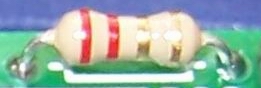
The fifth resistor orientation is "flat" ("flat-h" being horizontal and "flat-v" being vertical, with respect to the top edge of the board).
The pictures below illustrate these mounting techniques:
| Orientation | Silkscreen | As Mounted |
|---|---|---|
| East-West ("E-W") |

|
|
| West-East ("W-E") |

|
|
| North-South ("N-S") |

|
|
| South-North ("S-N") |

|
|
| Flat ("flat-h" or "flat-v") |

|
|
Ceramic Capacitors
If you get confused switching between pf and µF (or as we used to call them, "mmF and mF"), you can use this handy calculator. Values
Ceramic capacitor value codes are typically expressed as three digits where the first two digits are the significant figures of the capacitor value and the third digit indicates how many zeros to add to express the capacitor value in pF. Examples would be:
- code 471 would indicate a 470 pF capacitor code 2
- 20 would indicate a 22 pF capacitor.

| 1st Digit | 2nd Digit | Multiplier Code | Multiplier | Tolerance Code | Tolerance |
|---|---|---|---|---|---|
|
0 |
0 |
0 |
1 |
B |
± 0.1pF |
|
1 |
1 |
1 |
10 |
C |
± 0.25pF |
|
2 |
2 |
2 |
100 |
D |
± 0.5pF |
|
3 |
3 |
3 |
1,000 |
F |
± 1% |
|
4 |
4 |
4 |
10,000 |
G |
± 2% |
|
5 |
5 |
5 |
100,000 |
H |
± 3% |
|
6 |
6 |
|
|
J |
± 5% |
|
7 |
7 |
|
|
K |
± 10% |
|
8 |
8 |
8 |
0.01 |
M |
± 20% |
|
9 |
9 |
9 |
0.1 |
Z |
+80% / -20% |
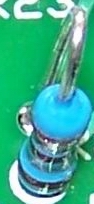
- Lightly snug each capacitor as close to the board as the lead formation will allow.
- Slightly spread the capacitor leads on the bottom side of the board and solder one lead to hold the capacitor in position.
- Cut both leads flush to the bottom of the board and solder the second capacitor lead.
SMT Capacitors
Caveat: Note that the SMT caps in the Softrock kits are of two types:
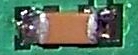
- 0.1 µF carrier strip (note black stripe
 )
) - 0.01 µF carrier strip (note: clear strip
 )
)
Most of the kits use both types. Do not get them mixed up!
All SMT capacitor locations on Softrock kit boards are to be filled with 1206 size capacitors. You want to do your work on a cookie sheet or other "pan" with sides so, if you accidentally sneeze or otherwise "launch" one of these tiny chips, you may still have a chance of retrieving it.
Removing Caps from the Carrier
Most SMT components are supplied on a "cut tape" carrier strip from a reel of parts. This tape is normally a paper or plastic backing with a clear plastic strip on top. Tony marks the 0.1 µF strip with a black stripe for identification.
The way that works best for most builders is to somehow get a grip on the plastic strip and carefully seperate from the main strip. This will leave the exposed parts sitting in indents in the backing. Sometimes rather than just get one or two, you can take off the entire plastic strip so it won't somehow knock the rest on the floor !! The real trick is getting the plastic strip started: you can use your exacto knife or even a probe tip jabbed in the plastic. Takie care to avoid having the natural "springiness" of the carrier strip act as a slingshot that could launch the loosened chips into the air
Installation procedure is as follows for each SMT 1206 Capacitor
- Add a little solder to one pad and tack one end of a capacitor to a pad.
- Reheat and position the capacitor with the tip of the soldering iron and a toothpick.
- When the capacitor is properly positioned on its pads, solder the other end with enough solder to make a small fillet between the end of the capacitor and the pad.
- < Reheat the first end of the capacitor and add a little solder, if necessary, to make a small fillet at the tacked down end of the capacitor.
-
Leonard KC0WOX has an excellent video on installing SMT Caps.
Another very good video on Youtube by Steve "Soldersmoke" Weber KD1JV is viewable below:
Return to top of page. SMT ICs
SMT Integrated Circuits
Electro Static Discharge (ESD) Precautions
These ICs are very sensitive and subject to being destroyed by electrostatic discharge. You must use common-sense, protective ESD precautions when handling or working with these chips, such as:
- Avoid carpets in cool, dry areas.
- Leave PC cards and memory modules in their anti-static packaging until ready to be installed.
- Dissipate static electricity before handling any system components (PC cards, memory modules) by touching a grounded metal object, such as the recommended uncoated metal cookie sheet.
- If possible, use antistatic devices, such as wrist straps and antistatic mats (see Radio Shack's Set for $25 or the JameCo AntiStatic mat for $15)).
- Always hold a PC card or memory module by its edges. Avoid touching the contacts and components on the ICs.
- Before removing chips from insulator, put on the wrist strap connected to the ESD mat. All work with CMOS chips should be done with the wrist strap on.
- As an added precaution before first touching a chip, you should touch a finger to a grounded metal surface.
- If using a DMM, its outside should be in contact with the ground of the ESD mat, and both leads shorted to this ground before use.
Installation procedure is as follows for each Surface Mount Technology (SMT) IC:
- Orient the IC on its pads so that the pin 1 corner of the IC matches the small 1 (it also looks like a 0) mark in the copper on the bottom side of the board. In general, pin 1 of an SOIC packaged IC is in the lower left corner of the package when the printing on the package top reads upright, from left to right.
- Tack-solder one corner pin of an IC and reheat the tacked pin as necessary to line up the IC on its pads properly.
- Check the orientation of the IC and the line up of the IC on its pads with magnification and good lighting.
- If all is well, carefully solder the rest of the leads to their pads.
- Carefully and closely inspect the pins to look for bridges caused by excessive solder or debris on or around the pads.
- Use solder wick to remove any excess solder or solder bridges between IC pins.
- Using high (3x or better) magnification, carefully check each pad and solder joint.
Leonard KC0WOX has an excellent video on installing surface mount ICs. The Sparkfun website also has some good video materials on soldering and wicking SMT ICs.
The video below describes techniques for soldering SOIC 14 (and 16 and 8) SMDs
View the above in full-screen mode on Youtube.
Return to top of page.Inductors - General Info
Inductors in the Softrock kits are generally wound by the builder on one of two different types of magnetic cores: Toroids or "Binoculars".
Toroidal Cores

 A Toroidal core is doughnut-shaped
and its color (usually either red or yellow) identifies the type of material.
Toroids are typically used for coils and
transformers.
The toroid's component identifier is of the form "Tdd-m",
where the "dd" refers to the outside diameter of the toroid in hundredths of an inch
and the "m" designates the material used. Some of the more common toroids found in
these kits are:
A Toroidal core is doughnut-shaped
and its color (usually either red or yellow) identifies the type of material.
Toroids are typically used for coils and
transformers.
The toroid's component identifier is of the form "Tdd-m",
where the "dd" refers to the outside diameter of the toroid in hundredths of an inch
and the "m" designates the material used. Some of the more common toroids found in
these kits are:
| Identifier | Color | Type Material | O.D. |
|---|---|---|---|
| T25-2 | Red | 2 | 0.25" |
| T25-6 | Yellow | 6 | 0.25" |
| T30-2 | Red | 2 | 0.3" |
| T30-6 | Yellow | 6 | 0.3" |
| T37-2 | Red | 2 | 0.37" |
| T37-6 | Yellow | 6 | 0.37" |
| T50-2 | Red | 2 | 0.5" |
| T50-6 | Yellow | 6 | 0.5" |
Binocular Cores
 Binocular cores are so-called because their shape calls mind
a pair of binoculars.
Binocular cores are typically used for chokes and
transformers.
These kits use binocular cores of two types:
Binocular cores are so-called because their shape calls mind
a pair of binoculars.
Binocular cores are typically used for chokes and
transformers.
These kits use binocular cores of two types:
If your kit calls for two different types of BN-*-2402 cores, take great care in keeping them separate and marked. The Softrock kits will always - in such case - provide the cores in separate, marked bags. DO NOT MIX THEM UP!
Preparing Binocular Cores for Winding
It is highly recommended to "debur" the holes on the binocular cores to allow for smooth insertion of the wires and avoid inadvertent shorts caused by rough edges to the holes. This can be done using a drill bit that just fits into the holes and "twirling" it between your fingers. Better still (as suggested by Iain,MW0XEN) use a mounted stone from a Dremel type tool (just held in your fingers - not powered). This leaves a very nice rounded edge to the holes.
Winding Specifications
Winding specifications provide the information on the number of windings, the role (e.g., primary or secondary) for each winding on a transformer, and the length and type of wire for the windings.
Specification Format
Winding specs will generally resemble the following:
5.0 uH 17T bifilar/34T #30 on T30-2 (red) (19").
This can be interpreted as:
- Use a T30-2 toroid (color is red and O.D. is 0.3")
- You will need two 19" lengths of #30 wire.
- For toroids, one turn is a single pass through the center hole.
- For binocular cores, one turn is a pass in which the wire goes in the bottom, comes out the top, goes back in the other hole at the top, and comes out the other hole at the bottom.
- The transformer will have a single, 34 turn, secondary winding of 19" of #30 wire. Usually the single winiding is wound onto the core first. Winding should be evenly spaced and ideally cover all but a 15 degree "wedge" of the toroid. Sometimes, it may be necessary to wind over the top of existing turns where there is more wire than there is bare core left.
- The transformer will have two primary windings each of 17 turns of #30 wire. The term "bifilar" means to take one of the two lengths of wire, bend it at the half-point so the resultant "hairpin" is composed of the two 9.5" long halves, and then twist the two strands together to make a "bifilar" strand with approximately 3 twists to the inch. The bifilar windings are usually wound AFTER (and over) the single strand winding. You should wait until you have wound it correctly before cutting the "hairpin" end of the bifilar strand.
- The inductance value is provided primarily to help validate the number of turns. It is the inductance of the single-strand winding.
Wires
Sometimes the various wires in the kit may be of different colors. Attach no significance to the color; recognize that when the spec calls for a #nn wire, that the "nn" is the gauge of the wire and the higher the gauge number, the thinner the wire.
See the sections below for further details on winding Toroidal and Binocular inductors.
Toroid Coils
Toroids
Identifying the toroids becomes simple once you figure out the coding. The toroids are designated using the pattern "T-NN-M". The critical pieces are the "NN", representing the outside diameter of the "donut" in hundredths of an inch, and the "M", representing the type of material used to make the core. Tony uses the following toroids in his kits:
- T30-2 (red)
- T37-2 (red)
- T25-2 (red)
- T25-6 (yellow)
- T30-6 (yellow)
Toroids are used in single-winding coils and multi-winding transformers. In either case, the number of turns must be counted. Any pass through the center of the Toroid is counted as a "turn" (see below).
Coils
The winding of a single-winding toroidal inductor is fairly straight-forward. Each pass through the center counts as a turn. The windings should be spaced evenly around the circumfrence of the toroid, ideally leaving about a 15 degree "wedge" between the beginning and ending of the winding. The image below is of a 22 turn coil wound on a toroid.
Occasionally, you may find that there is not enough room on the toroid to place all of the windings without having to go back and add a layer of winding. Tony Parks suggests that you overlap some turns as you put on windings around the circumference of the core so that all turns are on the core by the time you get back to the start end of the winding. This should have negligible effect on the coil's performance in the radio.
Alan Wolke, W2AEW has a very helpful 8 minute video on Youtube, showing his clever technique for winding toroidal coils using a "sawed-off" chopstick.
Alan also has another video showing how to wind a trifilar transformer of 10 turns:
Leonard, KC0WOX, also has an excellent (if large - 183 Mb!) video showing the winding of a 26 turn coil on a T-37 core. While the turns andcore size in the video are not used in any of the Softrock kits, the technique is essentially the same. The actual process of winding the core begins at about 8.5 minutes into the video.
Clockwise or Counterclockwise?
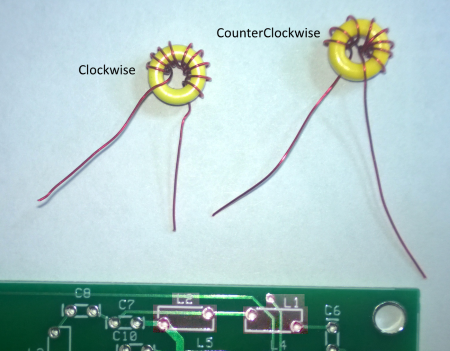
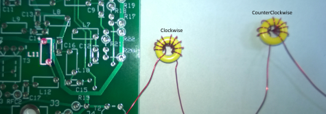
While the direction of winding of a toroidal coil really makes no difference so long as all windings on that core are in the same direction, it can make a difference in the physical placement of the finished coil on the circuit board. This picture shows two 10-turn coils, one wound clickwise and one wound counter-clockwise. It also shows a typical circuit Board and its silk-screened coil templates. Notice how the clockwise coil will fit correctly in the holes for L2, but will have an awkward fit to the holes for L1. Similarly, notice how the counterclockwise wound coil works for the L1 slot but only awkwardly for the L2 slot. If you wish to have your coils line up like the designer intended, you need to pay attention to the silkscreen slots and the hole positions, mentally trying to place a clockwise-wound coil vs. a counterclockwise-wound one into the slot. You can use these rules of thumb:
- If the coil template is horizontal and the left-hand hole is at the lower left, wind clockwise
- If the coil template is horizontal and the left-hand hole is at the upper left, wind counter clockwise
- If the coil template is vertical and the top hole is on the left, wind clockwise
- If the coil template is vertical and the top hole is on the right, wind counterclockwise
Toroidal Transformers
Winding toroidal transformers usually involves 2 to 3 windings on the same core. The most common is a transformer with a single winding (primary or secondary) over which two "bifilar" windings are superimposed (two secondaries or primaries). See the Toroid Winding Hints from the Experts for good tips on how to wind a toroidal transformer.
 In general the transformer outlines on the circuit boards, 4 hole or 6 hole patterns,
correspond to the shape of the core involved. The silkscreen lines between opposing
hole pairs correspond to the connections for one winding. All that is needed is to
connect the leads from one side of the core, or one hole of the core in the case of
the binocular cores, to the holes on one side of the pattern the the leads from the
other side of the core, or other hole of a binocular core, to the holes on the other
side of the pattern. Secondary and primary leads need to be sorted out properly.
In general the transformer outlines on the circuit boards, 4 hole or 6 hole patterns,
correspond to the shape of the core involved. The silkscreen lines between opposing
hole pairs correspond to the connections for one winding. All that is needed is to
connect the leads from one side of the core, or one hole of the core in the case of
the binocular cores, to the holes on one side of the pattern the the leads from the
other side of the core, or other hole of a binocular core, to the holes on the other
side of the pattern. Secondary and primary leads need to be sorted out properly.
When you have finished winding, stripping, and tinning the toroidal transformer's windings, you will two leads for each winding. Each lead will come out on a different side of the toroid. For example, consider a three-winding transformer with one primary ("P") and two secondary windings ("S1" and "S2"). It will have a total of six leads, three on one side of the toroid and three on the opposite side:
- The two primary leads, "Pa" and "Pb" ("P" stands for primary; "a" is one side of the toroid, "b" is the opposite side)
- The two leads for the 1st secondary winding, "S1a" and "S1b" ("S1" stands for the 1st secondary winding; "a" is one side of the toroid, "b" is the opposite side)
- The two leads for the 2nd secondary winding, "S2a" and "S2b" ("S2" stands for the 2nd secondary winding; "a" is one side of the toroid, "b" is the opposite side)
To mount the transformer you insert the leads into the holes annotated on the board as "P", "S1", and "S2". The holes may also be annotated as to the "row" ("a" row or "b" row) which corresponds to the leads on the "a" side or the "b" side of the toroid.
the builder should start with the single winding, inserting its two leads into the appropriate holes and then do the same with the first of the two bifilar windings, and finally do the same with the second of the two bifilar windings
After inserting the leads, the builder should pull each lead pair through the holesuntil the transformer is snug to the board. Soldering the leads completes the process.
Leonard, KC0WOX, has an excellent (large - 100+ Mb!) video showing the winding and mounting of a bifilar transformer on an earlier Softrock (transceiver) kit. He also has a 2 minute video clarifying how bifilar transformers are mounted on Softrock boards.
Return to top of page.Binocular Transformers
Debur the Core Before Winding
Binocular cores
Winding and Installing transformers on binocular cores is a hard process to clearly describe. There are two aspects to it.- One is the actual winding of the coil. Bino cores can be wound either:
- with all leads coming out of the same end or
- with some leads coming out of one end and some coming out of the other.
- All Tony's kits - so far - have used the winding convention where all windings come out of one end of the binocular core, with one turn counted each time the wire goes in one hole and comes out the other, at the same end (see below).
- The other aspect is the correct polarity. That is a little easier, since Tony has designed the
boards such that the polarity is pretty well handled for you.
- The key is to start each winding in the same hole of the bino core and end each winding in the other hole (on the same end of the core).
- When you finish winding the typical bino transformer with one single wire winding and one bifilar (i.e., twisted pair of wires) wire winding (yielding two windings), you have three wires coming out of each hole on the same end of the core, corresponding to the leads of the three windings.
- You should carefully strip the insulation from the leads (up to within an eighth of an inck of the core) and tin the leads. Sandpaper can be used to strip the insulation, or you can use an Exacto kinfe to scrape it off. Note that the insulation on the wire Tony provides is normally the heat-strippable type (which you can strip by repeatedly pulling the wire end through a HOT solder blob on the iron tip)..
- In most of Tony's kits the core is mounted "standing up" vertically and the windings' lead pairs are inserted into the holes corresponding to the winding.
- For example, if you wind a transformer with one primary (P) and two secondary windings (S1 and S2), you end up with three leads (Pa, S1a and S2a) coming out of one hole and three leads (Pb, S1b, and S2b) coming out of the other hole.
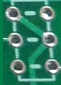
- The board layout in the enhanced builders notes will usually have annotations on the six holes (for a common transformer) that indicate the lead pairs for the primary, and each of the 2 secondaries.
- The builder then needs to match the holes with the appropriate winding leads. This graphic is an example:
- T201 (above) has one primary and two secondary windings.
When wound, it will have 6 leads in all:
- two leads (Pa and Pb) and
- four secondary leads (S1a, S2a, S1b, S2a).
- You should use an ohmmeter to identify each winding pair.
Then slip a 1/8" pice of hookup wire insulation onto the Pa and Pb leads to temporarily provide identification
of the primary. Also slip a 1/8" piece of insulation onto the S1a and S1b leads to act as a "spacer for the
actual mounting.
- To mount the core, the builder typically starts with the Primary leads, removing the insulation piece and
orienting the core such that (in the above instance):
- the core hole from which Pa lead exits is aligned with the P hole on the top row of the holes and
- the core hole from which the Pb lead exits is aligned with the P hole on the bottom row.
- Then insert those primary leads into their corresponding holes.
- Then take the first pair of S leads (e.g., S1a and S1b) and similarly align with and insert into the "S1" holes (S1a on the top and S1v on the bottom row of holes in the graphic above).
- Finally do the same thing with the remaining lead pair (S2a and S2b).
- Then pull through all of the leads from the bottom of the board to ensure no leads have any loose ends or loops topside and the transformer is nice and snug on the board and the 1/8" spacer
- Solder all leads and you're ready to test them.